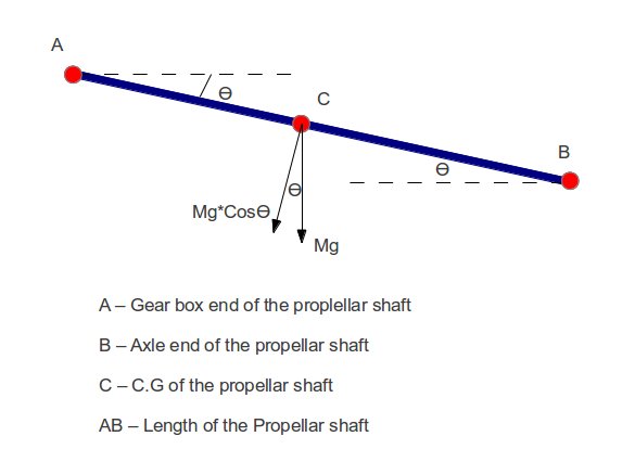
Calculation of Bending Moment Effect. In case of two or multi stage propeller shaft length of the rear propeller shaft change in length.
Drive Shaft Design Calculation For Automobile
Outer Diameter of section.

. Ad Find the perfect propeller for your boat to enhance the use in any application. This free propeller shaft size calculator helps you determine the proper propeller shaft diameter for your boat. Shaft horsepower is converted to a rotary force or moment applied to the propeller.
61 DIMENSIONS OF THE PROPELLER SHAFT Length of the shaft. To simplify this above calculation process we can find the least critical shaft diameter by using the following T e formula used for the shaft subjected to fluctuating and twisting and bending together. Design of propeller shaft for reduction in weight.
Bending moment occurs because of the own weight of the shaft. J fracVnd frac6173316times17 115. Shaft powerr delivered PD 1937 10 3 hp.
The propeller is keyless fitted on to the shaft taper by a shrinkage method in compliance with Ch 1 8ec 8 312 or the propeller boss is attached to an integral propeller shaft flange in compliance. Marine Propeller Shaft Calculations Propeller Shaft designing requires inputs such as engine power engine speed output power and speed range to be attained gearbox parameters etc. Ad Browse discover thousands of brands.
The propeller shaft is geared down by a ratio of 227. Static deflection is calculated from the equation. Get the Deals now.
SkyCiv offers a wide range of Cloud Structural Analysis and Design Software for engineers. δ 5mgcos θ L3384EJ 0036579 mm. Designing involves finding diameter of the propeller shaft both tail shaft and intermediate shaft.
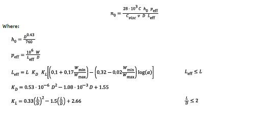
128661 mm2 Position of centroid - X. The calculator utilizes the following industry accepted formula endorsed by. Computer Aided Design of propeller shaft in Solidworks software.
11 Propeller Diameter in inches. The calculation goes as below. Free Online Shaft Calculator Sam Carigliano 2020-08-19T1548451000.
Design of Propeller Shaft Flanges Thickness of flange 025 d 5 027 x 500 T 140 mm Mass of flange excluding shaft 4 x dp2 d j 2 xtf xp dp 500 mm BENDING MOMENT CALCULATION For Propeller Shaft R aft R fwd 1471 x 4980 646293 155653 23537173 1 R fwd x 3040 64629334 x 431333 155653 x 66667 0 666671471 dx 0. The propeller is keyed on to the shaft taper in compl i- ance with the requirements of 255 kp 122 for propeller shafts where. D 3 2013164.
Aim of this project is to design analyze and simulate a propeller shaft which is optimized with respect to weight strength and reliability. You just need to enter the required values inside the brackets then click on the Calculate button to see the result. 10 13 Propeller Pitch in inches.
162 Objective The objectives of this project are. Calculate maximum static deflection of the driveshaft δ. Calculation of shafts in marine applications DNV GL AS Figure 2 Hysteresis loops of plastification in the notch Simplified diameter formulae are presented in the RU SHIP Pt4 Ch4 Sec1 226 to RU SHIP Pt4 Ch4 Sec1 228 for various common shaft designs.
As a constantly evolving tech company were committed to innovating and challenging existing workflows to save engineers time in their work processes and designs. 40 mm Thickness of the hollow shaft. Ad Best Deals On Propeller Shaft.
42 Design of propeller shaft. The calculator determines a safety factor design coefficient based on shaft diameter max engine RPM shaft horsepower gear ratio and torsion strength of the shaft material used. Length of shaft L1250 mm.
Kp 126 for propeller shafts where. Used to rotate the shaft connected between the engine and the propeller. This means 33 of the disc area of prop dia is blades.
Inclination angle θ2 Deg. 1581139 7854 d 3. However since the simplifications are made to the safe.
38205 mm Position of centroid -. This rotary force necessary to turn the shaft is simply torque. Read customer reviews find best sellers.
The stresses referred to are principal stresses. The designing shall be done after determining all the input parameters. 7614 mm Inner Diameter of section.
1730 mm Mean radius of the shaft. Torque Force length Nm Power Force Velocity Force length angular velocity. This is an automatic calculation from shaft horsepower and rpm at prop on Torque sheet.
In this part of the automobile propeller shaft design calculation tutorial we will see the critical speed calculation procedure for the example problem. Multistage propeller shaft the intermittent pieces are supported by center bearings which are mounted on the bracket of cross member 2. σA dynamic stress amplitude S safety factor U fatigue strength amplitude.
Design of propeller shaft Calculation for Moment of Inertia of propeller shaft. Design of Shafts 1. Order today with free shipping.
From this we can T e 1581139 Equate this to the above 7854 d 3. 6481 Area of section. RameshSingh Introduction Torque and Power Transmission Most of rotary prime movers either motors or turbines use shaft to transfer the power Bearings are required for support Shaft failure analysis is critical 2.
Transferred Torque T3500 Nm. The bending moment must be calculated according to the. The following example will be taken as a sample drive shaft design problem throughout this series of article.
If you want to make another calculation just click on the Reset button then re-enter the new values. Use the B 5-90 prop curve to determine KT and KQ KT 12 KQ 023 Thrust KT ρ n 2 d 4 Thrust 2654 10 4 lb b. SECTION 2 CALCULATION OF HIGH CYCLE STRESSES IN PROPELLER BLADES 1 High cycle stress criterion Dynamic stress amplitudes in the propeller blade shall fulfil the following criterion.
4578 mm Carbonepoxy shaft. Design a cardon shaft with the orientation shown as below. Automobile Propeller Shaft Design Example Arrangement.
Rps_prop frac7167227316 rps The advance ratio follows. 4 FEA model of the composite propeller shaft. In the case of hollow circular cross section stress variation is small.
Shaft Torque Torque KQ ρ n 2 d 5 Torque 5087 10 4 lb ft PD 2 π n Torque 550 lb ft sec hp c. 5110 mm Glassepoxy shaft Fig. The variation in the length of rear propeller shaft is allowed using a splined shaft 1.
15 033 mean-width ratio blades.

Propeller Shaft And Drive Shaft Automobile

Design And Optimization Of Automobile Propeller Shaft With Composite Materials Using Fem Analysis Semantic Scholar
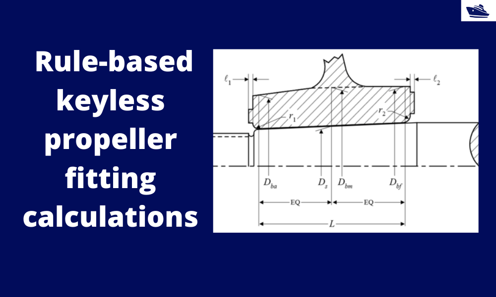
How To Do Rule Based Fitting Calculations Of A Keyless Propeller Thenavalarch

Propeller Shaft And Drive Shaft Automobile
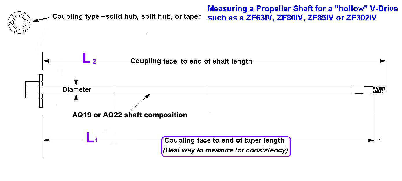
How To Measure The Propeller Shaft And Propeller Shaft Coupling Seaboard Marine

Lloyd S Register The Shaft Calculation Software By Imt
Dnv Gl The Shaft Calculation Software By Imt

Propeller Shaft And Drive Shaft Automobile
0 comments
Post a Comment